BMW 7 ser. E65, E66 & E68 Wiring Diagram System
BMW 7 Series E65, E66 & E68 Wiring Diagram System - Complete guide with electrical diagrams for the BMW 7 Series E65, E66 and E68 models. Includes detailed wiring diagrams, circuit descriptions and component locations to accurately diagnose and troubleshoot your vehicle's electrical system.
Wiring Diagrams and Functional
Wiring diagrams include location information, wiring, pin identification, troubleshooting, maintenance, function descriptions, and more. This includes all information that follows wiring and wire connections.
Language: English
Format: ISO Image
Size: 2 Gb
SeatsControl-E65
TEC-6302-9 Technical Manual for SeatsControl-E65 module
Unit port outputs assignment
Standart delivery kit
BMW E65 Installation Instructions Manual
Advanced DVD system with multimedia changer retrofit
BMW 7 Series Saloon (E65 / E66)
System circuit diagram
Energy management E65/E66MU

Index Description
1 Alternator
2 Starter
3 Digital Motor Electronics DME
4 Jump start terminal point
5 Fuse box, engine compartment
6 Power distribution box, front
7 B-pillar satellite, right
8 Battery switch
9 Interior lights button
10 Boot lid button
11 Fuse (250 A)
12 Safety battery terminal
13 Battery
14 Power module
15 Power distribution box, rear
16 Terminal 30 for emergency siren and infrared remote control
17 Central locking of fuel tank flap
18 Central locking of boot lid
Index Description
19 Soft Close Automatic
20 Load/consumer deactivation, body (VA_K)
21 Load/consumer deactivation, roof, front and rear (VA_D)
22 Interior lights (IB)
23 Safety and Gateway Module SGM
24 Remote control receiver FBD
25 Light Module LM
26 Instrument cluster
27 Car Access System CAS
28 Anti-theft alarm system DWA
PT-CAN Power Train Controller Area Network
K-CAN Body Controller Area Network
Kl. 30B Continuous positive
Kl. 30Ug Continuous positive
Kl. 30SV Terminal 30 Special loads/consumers
Kl. R Terminal R
Kl. 15 Terminal 15
WUP Wake-up line
Functions
Changes in energy management
The CAS and DME control units are no longer powered by separate outputs on the power module. These control units are combined together with the light module, the instrument cluster and the remote control receiver on a common connection.
This output is known as Terminal 30 Special loads/consumers (Kl. 30SV). This terminal can be switched by means of a hardware alteration in the power module
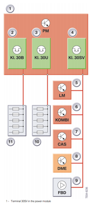
Index Explanation
1 Power module
2 Terminal 30B
3 Terminal 30U
4 Terminal 30SV (Special loads/
consumers)
5 Light Module LM
6 Instrument cluster
7 Car Access System CAS
8 Digital Motor Electronics DME
9 Remote control receiver
10 Power distribution box, rear
11 Power distribution box, front
Exterior lighting E65/E66MU

markel (Wednesday, 03 December 2025 21:45)
I need it please.