
BMW F30 Full Wiring Diagram. Electrical system

Complete wiring diagrams for the BMW 3 Series F30/F31 (2011–2019). An indispensable guide for diagnosing and troubleshooting complex electrical systems. Includes wiring diagrams for:
- Engine and ECU (N20, N47, N55, B-series).
- Safety systems (ABS, DSC, Airbag).
- Convenience electronics (iDrive, lighting, Comfort Access).
Contains precise component locations and grounding.
BMW F30 Wiring Diagram
| Password For Document: bimmer-service.com | |
| General vehicle electrical system, check | Download |
| Wiring harness, Installing repair cable | Download |
| Auxiliary cable | Download |
| Plug connection, terminal | Download |
| Power distribution box, current terminals. fuse box | Download |
| Battery. Battery with holder | Download |
| High-voltage accumulator system. Voltage transformer | Download |
| Switch, sensor location | Download |
| Horn. Removing and Installing | Download |
| Cigarette lighter, 12 V connections | Download |
| Control Units, Modules | Download |
| Relay. Removing and Installing | Download |
| Voltage transformer | Download |
| Windscreen wipers. Rear wiper. Windscreen washer system | Download |
| Headlight cleaning system | Download |
| Lights system | Download |
| Audio, navigation, information systems Wiring Diagram | Download |
| Electric motor | Download |
BMW F30 335i Engine Electrical system (N55)
| Password For Document: bimmer-service.com | |
| Engine electrical system. Instruction for removal and replacement of control units | Download |
| Ignition lead, spark plugs | Download |
| Ignition coil | Download |
| Electronic Shift Units or Control Units | Download |
| Alternator with Drive and Mounting Parts | Download |
| Starter motor with mounting | Download |
| Starter line | Download |
| Engine wiring harness | Download |
| Oil pressure, oil temperature, oil level display | Download |
| Switches and relays (N20, N26, N55) | Download |
voltage bus structure
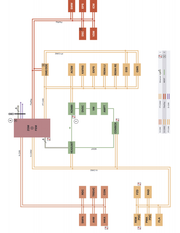
Activating bus system control units
2 Nodal start-up control blocks for starting and
FlexRay bus system synchronization
ACSM Crash Safety Module
AHM Trailer Electrical Connection Module
AMPT Top HiFi Amplifier
COMBOX Combox communication station (emergency call Combox communication station,
multimedia communication stations Combox)
CON Controller
D-CAN Diagnostic CAN
DDE Digital Electronic Diesel Engine Management
DME Digital Engine Electronics
DSC Dynamic Stability Control
DVDC DVD changer
EGS Electronic Transmission Control
EKPS Fuel Pump Control System
EPS Electromechanical power steering
Ethernet Ethernet bus
FEM Front Electronic Module
FLA Headlight High Beam
FlexRay Chassis Management Bus
FZD Roof Functional Center
GWS Gear Shift
HEADUNIT Head Unit (Car Information Computer or Head Unit
Basis)
ICM Integrated Chassis Management
IHKA Integrated automatic heating and air conditioning
K-CAN Body CAN
K-CAN2 Body CAN 2
KAFAS Camcorder Driving Assistance Systems
KOMBI Instrument cluster (MOST bus only with SA 6WA)
MOST Data bus between ICT systems
OBD On-Board Diagnostic System (Diagnostic Connector)
PDC Parking Approach Alarm (with SA 5DP Parking
Assistant - built into the control unit of the parking assistant; in other
cases - to the REM module)
PMA Parking Assistant
Onboard network
FlexRay F30 System Diagram
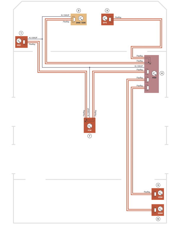
Designation Explanation
1 Dynamic Stability Control (DSC)
2 Digital Engine Electronics (DME) or
Digital Electronic Diesel Engine Management (DDE)
3 Electromechanical power steering (EPS)
4 Front Electronic Module (FEM)
5 Vertical Dynamics Management (VDM)
6 Hazard warning control unit
rebuilding (SWW)
7 Integrated Chassis Management (ICM)
Power system

Designation Explanation
1 Power Distribution Module (PDM) (only for vehicles with
gasoline engine)
2 Generator
3 Digital Engine Electronics (DME) or
Digital Electronic Diesel Engine Management (DDE)
4 Starter
5 electric fan
6 electric fan relay
7 Output (B +) for connecting an external power source
8 Front power distribution box
9 Power distribution box in the engine compartment
10 Front Electronic Module (FEM)
11 Rear Electronic Module (REM)
12 Power distribution box in the luggage compartment
13 Emergency Stop (SBK) terminal
14 Battery
15 Intelligent Battery Sensor (IBS)
16 Battery distribution box
17 Crash Safety Module (ACSM)
Kl. 30 Standing Plus
Kl. 30B Contact 30B
Kl. 15N Pin 15N
Kl. 30F Contact 30F
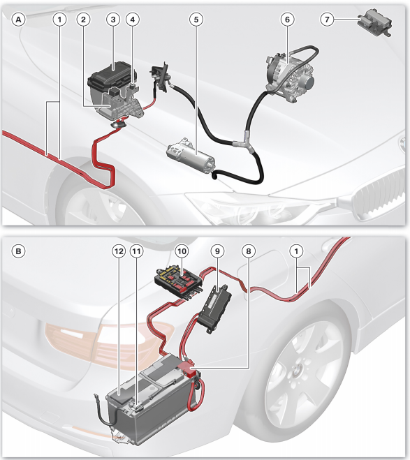
Designation Explanation
A Front Power Components
B Rear power components
1 Main battery wires
2 Front power distribution box
3 Power distribution box in the engine compartment
4 Output (B +) for connecting an external power source
5 Starter
6 Generator
7 Power Distribution Module (PDM)
8 Emergency Stop (SBK) terminal
9 Battery distribution box
10 Power distribution box in the luggage compartment
11 Intelligent Battery Sensor (IBS)
12 Battery
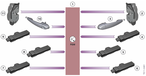
Comfort access system.
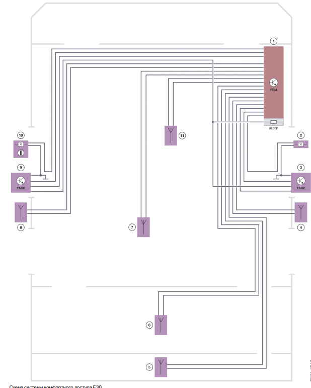
Designation Explanation
1 Front Electronic Module (FEM)
2 Front passenger door contact
3 Front passenger door door handle electronics (TAGE)
4 Antenna comfort access system on the right threshold
5 Antenna comfort access system in the rear bumper
6 Antenna for comfort access system in the luggage compartment
7 Rear access aerial
8 Antenna comfort access system in the left threshold
9 Driver Side Door Handle Electronic Assembly (TAGE)
10 Driver door contact
11 Antenna for comfort access system in front of the passenger compartment
Kl. 30F Contact 30F
The electronic components for the TAGE exterior door handles are also read by the FEM.
1 Front Electronic Module (FEM)
2 Front passenger door contact
3 Front passenger door door handle electronics (TAGE)
4 Antenna comfort access system on the right threshold
5 Rear access aerial
6 Antenna for comfort access system in the luggage compartment
7 Antenna comfort access system in the rear bumper
8 Front access aerial
9 Antenna comfort access system in the left threshold
10 Electronic driver's door handle electronic assembly (TAGE)
11 Driver door contact
Central castle.
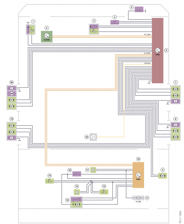
Designation Explanation
1 Key for unlocking the boot lid (in some versions
set as standard)
2 Instrument cluster (KOMBI)
3 central locking button / emergency light switch
alarm
4 “Hotel” position switch (US version only)
5 bonnet contact
6 Front Electronic Module (FEM)
7 Door contact, central lock, right front door
8 Door contact, central locking of the right rear door
9 Central locking fuel filler flap
10 Rear Electronic Module (REM)
11 Power distribution box in the luggage compartment
12 Contact switch for boot lid with boot lid lock
13 Lantern in the boot lid (only with lighting package
equipment, SA 563)
14 Lantern in the boot lid (only without lighting package
equipment, SA 563)
15 Lantern in the boot lid (only with lighting package
equipment, SA 563)
16 Button on the trunk lid outside
17 Luggage compartment light (basic: lamp
Incandescent. With SA 563: LED)
18 Remote control receiver
19 Door contact, central locking left rear door
20 Door contact, central locking of the left front door
Kl. 30B Contact 30B
Power windows.
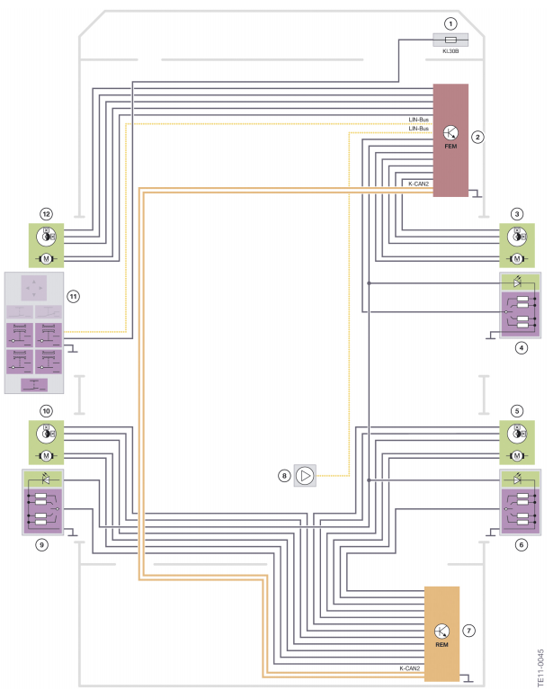
Designation Explanation
1 Power distribution box in the engine compartment
2 Front Electronic Module (FEM)
3 Power window front passenger door with
indirect injury protection function
4 power window switch, front passenger door
5 Power window right rear door with indirect
injury protection function
6 Power window switch, right rear door
7 Rear Electronic Module (REM)
8 Remote control receiver
9 Power window switch left rear door
10 Power window left rear door with indirect
injury protection function
11 Switch block in the driver's door
12 Power window driver door with indirect
injury protection function
Kl. 30B Contact 30B
Harry (Wednesday, 09 April 2025 12:52)
Ac wiring diagram
alaa (Monday, 01 January 2024 09:17)
yes
Camiel (Wednesday, 18 January 2023 22:00)
Awesome info for repairs0
TzwSVsOw (Friday, 30 December 2022 14:51)
20