
Detailed pinout of the DME MS45.1 unit for BMW M54 6-cylinder engines (E46, E39, E60). Terminal tables, VANOS, DISA, and sensor wiring diagrams.
Engine: M54B25, M54B30
Model: E60 525i, 530i, 545i
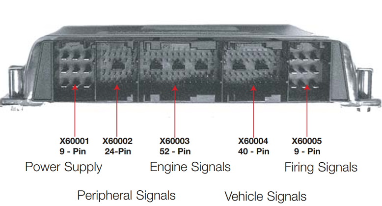
DME MS45.1 Pinout
X60001
| Pin | Type | Name | Wire | Description | Connection / Measuring notes |
|---|---|---|---|---|---|
| 1 | U | U_15 | 0.5 GN | Relay, fuel injectors | |
| 2 | A/E | – | – | – | Transmission Control Unit |
| 3 | D | T_TXD2 | 0.5 WS/VI | Signal, TXD | |
| 4 | M | 31E | 1.5 BR/OR | Ground | Terminal 31 support, E-box |
| 5 | M | 31L | 1.5 BR | Ground connector | |
| 6 | M | 31L | 1.5 BR | Ground connector | |
| 7 | E | 30H<102 | 1.5 RT | Supply, terminal 30 | B+ potential distributor |
| 8 | U | U_HR<2 | 1.0 RT/WS/GE | Supply, terminal 87 | Fuse carrier, engine electronics |
| 9 | – | – | – | – |
X60002
| Pin | Type | Name | Wire | Description | Connection / Measuring notes |
|---|---|---|---|---|---|
| 1 | A | T_LHV1 | 0.5 GN | Negative activation, oxygen sensor heating | Oxygen sensor 1 before catalytic converter |
| 2 | A | T_LHV2 | 0.5 GN | Negative activation, oxygen sensor heating | Oxygen sensor 2 before catalytic converter |
| 3 | A/E | D_CAN_L | 0.5 GE/BR | Signal, CAN low | CAN-bus connector (Transmission Control Unit) |
| 4 | A/E | D_CAN_H | 0.5 GE/SW | Signal, CAN high | CAN-bus connector (Transmission Control Unit) |
| 5 | – | – | – | – | |
| 6 | A | T_LHH1 | 0.5 BR | Negative activation, oxygen sensor heating | Oxygen sensor 1 after catalytic converter |
| 7 | M | LSV1 | 0.5 SW | Negative signal, oxygen sensor | Oxygen sensor 1 before catalytic converter |
| 8 | M | LSH2 | 0.5 GE | Negative signal, oxygen sensor | Oxygen sensor 2 after catalytic converter |
| 9 | E | M_LSV2 | 0.5 SW | Negative signal, oxygen sensor | Oxygen sensor 2 before catalytic converter |
| 10 | E | M_LSH1 | 0.5 GE | Negative signal, oxygen sensor | Oxygen sensor 1 after catalytic converter |
| 11 | – | – | – | – | |
| 12 | A | T_LHH2 | 0.5 BR | Negative activation, oxygen sensor heating | Oxygen sensor 2 after catalytic converter |
| 13 | E | LSVP1 | 0.5 BL | Signal, oxygen sensor | Oxygen sensor 1 before catalytic converter, only with MS45.1 |
| 14 | A | A_LSH2 | 0.5 GE | Signal, oxygen sensor | Oxygen sensor 2 after catalytic converter |
| 15 | E | LSVP2 | 0.5 BL | Signal, oxygen sensor | Oxygen sensor 2 before catalytic converter, only with MS45.1 |
| 16 | A | A_LSH1 | 0.5 GE | Signal, oxygen sensor | Oxygen sensor 1 after catalytic converter |
| 17 | – | – | – | – | |
| 18 | – | – | – | – | |
| 19 | A | LSVP1 | 0.5 OR | Signal, oxygen sensor | Oxygen sensor 1 before catalytic converter, only with MS45.1 |
| 20 | E | LSVR1 | 0.5 GE | Signal, oxygen sensor | Oxygen sensor 1 before catalytic converter |
| 21 | A | LSVP2 | 0.5 OR | Signal, oxygen sensor | Oxygen sensor 2 before catalytic converter, only with MS45.1 |
| 22 | E | LSVR2 | 0.5 GE | Signal, oxygen sensor | Oxygen sensor 2 before catalytic converter |
| 23 | S | S_HR | 0.5 BR/SW | Supply, terminal 87 | DME relay |
| 24 | – | – | – | – |
X60003
| Pin | Type | Name | Wire | Description | Connection / Measuring notes |
|---|---|---|---|---|---|
| 1 | E | A_HFM | 0.5 GE | Signal, hot-film air mass meter | Hot-film air mass meter |
| 2 | P | KWG | 0.5 GE | Signal, crankshaft sensor | Crankshaft sensor |
| 3 | A | HFMERF | 0.5 WS | Supply, air-mass flow meter | Hot-film air mass meter |
| 4 | U | DKG | 0.75 BR/WS | Supply, electric throttle valve | Throttle valve motor |
| 5 | A | P_EV2 | 0.75 BR/VI | Signal, fuel injector | Fuel injector, cylinder 2 |
| 6 | A | P_EV4 | 0.75 BR/RT | Signal, fuel injector | Fuel injector, cylinder 4 |
| 7 | A | P_EV6 | 0.75 BR/VI | Signal, fuel injector | Fuel injector, cylinder 6 |
| 8 | – | – | – | – | – |
| Pin | Type | Name | Wire | Description | Connection / Measuring notes |
|---|---|---|---|---|---|
| 9 | A | T_NWA1 | 0.5 GN/VI | Signal, VANOS valve | VANOS solenoid valve, exhaust |
| 10 | A | T_NWA2 | 0.5 GN/BL | Signal, VANOS valve | VANOS solenoid valve, intake |
| 11 | P | EV5 | 0.5 BR/RT | Signal, fuel injector | Fuel injector, cylinder 5 |
| 12 | P | S_FK7 | 0.5 GE/R | Signal, characteristic map thermostat heating | Characteristic map thermostat |
| 13 | A | P_EV1 | 0.75 BR/WS | Signal, fuel injector | Fuel injector, cylinder 1 |
| 14 | M | ANALOG | 0.5 SW | Ground, analogue | Hot-film air mass meter |
| 15 | E | M_DKG | 0.5 BR/GR | Ground, electric throttle valve | Throttle valve motor |
| 16 | S | S_OLD | 0.5 BR/GN | Signal, oil pressure switch | Oil pressure switch |
| 17 | – | – | – | – | – |
| 18 | E/A | D_BSD | 0.5 BL | Bi-directional data interface | BSD alternator |
| 19 | – | – | – | – | – |
| 20 | A | T_TEV | 0.5 BR | Signal, fuel tank vent valve | Fuel tank vent valve |
| 21 | A | T_LLSFS | 0.5 WS/GN | Signal, idle actuator | Idle actuator |
| 22 | A | T_LLFSO | 0.5 WS/GE | Signal, idle actuator | Idle actuator |
| 23 | – | – | – | – | – |
| 24 | A | P_EV3 | 0.75 BR/GE | Signal, fuel injector | Fuel injector, cylinder 3 |
| 25 | A | T_ATMS | 0.5 GE/RT | Signal, intake air temperature | Hot-film air mass meter |
| 26 | M | NWS1 | 0.5 BR/RT | Ground, coolant temperature sensor | Engine coolant temperature sensor |
| 27 | P | NMWGE1 | 0.5 GE | Signal, camshaft sensor | Camshaft sensor I |
| 28 | P | NMWGE2 | 0.5 GE | Signal, camshaft sensor | Camshaft sensor II |
| 29 | A | A_DKG2 | 0.5 BR/VI | Signal, throttle valve position | Throttle valve motor |
| 30 | A | A_KS1B | 0.5 GE/BR | Signal, knock sensor | Double knock sensor |
| 31 | A | A_KS2B | 0.5 BR | Signal, knock sensor | Knock sensor 2 |
| 32 | E | M_NWS2 | 0.5 BR/OR | Ground, coolant temperature sensor | Engine coolant temperature sensor |
| 33 | E | A_MWG2 | 0.5 GE | Signal, camshaft sensor | Camshaft sensor II |
| 34 | E | D_KWS | 0.5 BR | Ground, crankshaft sensor | Crankshaft sensor |
| 35 | S | S_DKA | 0.5 BR | CAN terminal resistor (only with M56) | CAN terminal resistor (M56 only) |
| 36 | S | S_SLV | 0.5 BR/WS | Signal, secondary air pump valve | Secondary air pump valve |
| 37 | S | S_DSIA | 0.5 BR/LB | Valve, individual control intake system | – |
| 38 | – | – | – | – | – |
| 39 | A | T_MDK1 | 0.75 GR/WS | Signal, actuator for electric throttle valve | Throttle valve motor |
| 40 | A | T_MDK2 | 0.75 GR/SW | Signal, actuator for electric throttle valve | Throttle valve motor |
| 41 | E | A_TOEL | 0.5 RT/BL | Signal, oil temperature sensor | Oil temperature sensor |
| 42 | E | A_OELS | 0.5 BR | Signal, coolant temperature sensor | Oil temperature sensor |
| 43 | A | T_KL1 | 0.5 GE | Signal, rear seat heating relay | – |
| 44 | A | A_KSA2 | 0.5 GE | Signal, knock sensor | Double knock sensor |
| 45 | A | A_KSW2 | 0.5 GE | Signal, knock sensor | Double knock sensor |
| 46 | M | NMWG1 | 0.5 BR | Camshaft sensor ground | Camshaft sensor II |
| 47 | E | A_OLN | 0.5 GR/BL | Signal, oil level sensor | Oil level sensor |
| 48 | E/A | D_LOCALN | 0.5 GE | Signal, CAN low | CAN terminal resistor, only with M56 |
| 49–52 | – | – | – | – | – |
X60004
| Pin | Type | Name | Wire | Description | Connection / Measuring notes |
|---|---|---|---|---|---|
| 1 | |||||
| 2 | A | S_DMTLH | 0.75 SW/RT | Activation, fuel tank leakage, heating | Diagnostic module, fuel tank leakage, only with MS45.1 |
| 3 | A | S_SLP | 0.35 BR/BN | Signal, secondary air pump | Secondary air pump relay |
| 4 | A | T_ELUE | 0.5 SW/GN | Signal, electric fan | Electric fan |
| Pin | Type | Name | Wire | Description | Connection / Measuring notes |
|---|---|---|---|---|---|
| 5 | M | M_SHFM | 0.5 SW/GE | Negative supply Secondary air - hot-film air-mass meter | Secondary air - hot-film air-mass meter, only with MS45.1 |
| 6 | M | M_FWG1 | 0.35 BR/GN | Ground, accelerator pedal position sensor | Accelerator pedal module |
| 7 | E | A_FWG1 | 0.35 WS | Signal, accelerator pedal position sensor | Accelerator pedal module |
| 8 | A | U_FWG1 | 0.35 GE | Supply, accelerator pedal position sensor | Accelerator pedal module |
| 9 | A | S_EKP | 0.35 SW/VI | Activation, fuel pump relay | Fuel pump relay |
| 10 | M | M_FWG2 | 0.35 BR | Ground, accelerator pedal position sensor | Accelerator pedal module |
| 11 | E | A_FWG2 | 0.35 WS/GN | Signal, accelerator pedal position sensor | Accelerator pedal module |
| 12 | A | U_FWG2 | 0.35 GE/GN | Supply, accelerator pedal position sensor | Accelerator pedal module |
| 13 | E | A_SHFM | 0.5 SW/RT | Signal, secondary air/hot-film air mass meter | Secondary air - hot-film air-mass meter, only with MS45.1 |
| 14 | A | TD | 0.35 SW | Speed signal | OBDII socket |
| 15 | A | S_AKL | 0.5 GR/VI | Signal, exhaust flap | Exhaust flap solenoid |
| 16 | A | S_EBOX | 0.5 BR/OR | Signal, E-box fan | E-box fan |
| 17 | A | S_DMTLP | 0.75 BR/BL | Activation, fuel tank leakage pump | Diagnostic module, fuel tank leakage, only with MS45.1 |
| 18 | A | S_GLF | 0.5 BR/WS | Signal, radiator shutter solenoid | Solenoid, radiator shutter |
| 19 | E | F_DFAHR | 0.35 WS/GN | Signal, processed wheel speed, rear right | Connector X10186 (rear right wheel speed) |
| 20 | E | S_KUP | 0.35 BL/BR | Signal, clutch switch | Clutch switch |
| 21 | E | S_BLS | 0.35 BL/RT | Brake light signal | Brake light switch |
| 22 | E | S_EAC | 0.5 BL/GE | Signal, EAC sensor | EAC sensor, only with M56 |
| 23 | E | 15229 | 0.5 GN/SW | Wake-up signal, terminal 15 | Connector, terminal 15 wake-up signal |
| 24 | A/E | FGRS | 0.35 BL/GR | Signal, Data Link Multi Function Steering Wheel | Volume Spring Steering Wheel |
| 25 | E | S_BLTS | 0.35 BR/GR | Brake light test signal | Brake light switch |
| 26 | A | S_KOREL | 0.5 SW/BL | Activation, A/C compressor relay | A/C compressor relay |
| 27 | A | S_DMTLV | 0.5 SW/GN | Activation, fuel tank leakage valve | Diagnostic module, fuel tank leakage, only with MS45.1 |
| 28 | A/E | D_LOCAL | 0.5 GN | Signal, CAN low | Fuel pump control (EKPS), only with M56 |
| 29 | A/E | D_TXD2 | 0.5 WS/N | Signal, TXD | OBDII socket |
| 30 | E | D_EWS | 0.35 SW/VI | Signal, electronic vehicle immobilizer | EWS / Car access system |
| 31 | A/E | D_LOCALH | 0.5 BL/GN | Signal, CAN high | Fuel pump control (EKPS), only with M56 |
| 32 | A/E | D_CAN_H | G |
|
X60005
| Pin | Type | Name | Wire | Description | Connection / Measuring notes |
|---|---|---|---|---|---|
| 1 | A | P_ZSZ5 | 1.5 SW/RT/WS | Signal, ignition coil | Ignition coil, cylinder 5 |
| 2 | |||||
| 3 | A | P_ZSZ3 | 1.5 SW/GE | Signal, ignition coil | Ignition coil, cylinder 3 |
| 4 | M | 31L | 2.5 BR | Ground | Terminal 31 support, E-box |
| 5 | A | P_ZSZ1 | 1.5 SW/WS | Signal, ignition coil | Ignition coil, cylinder 1 |
| 6 | A | P_ZSZ2 | 1.5 SW/RT | Signal, ignition coil | Ignition coil, cylinder 2 |
| 7 | A | P_ZSZ4 | 1.5 SW/BL | Signal, ignition coil | Ignition coil, cylinder 4 |
| 8 | A | P_ZSZ6 | 1.5 SW/VI | Signal, ignition coil | Ignition coil, cylinder 6 |
System Components / Functions
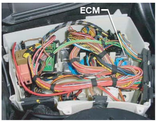
MS45.1 Engine Control Module: The ECM is located in the under hood E box (below).
The following modified controls / functions have been made to MS45.1 for use in the E60.
• New hot film air mass sensor (HFM).
• Changed data record variant (matched to E60).
• Lead to the CAS for start enable (starting relay is integrated in the CAS). (automatic/SMG
transmissions only).
• The Driving Dynamics control (FDC) signal is transmitted via the PT-CAN.
• The cruise control (FGR) signal is sent from the MFL via the PT-CAN to the ECM.
• Connection of the intelligent battery sensor (IBS) to the bit-serial data interface (BSD).
• The software for power management (vehicle electrical system) is integrated in the ECM.
• The A/C compressor is activated via the PT-CAN.
• Fault diagnosis is performed through the SGM via the PT-CAN to the ECM.
• Activation of the ECM main relay (525i / 530i in E box, 545i in IVM).
• Bosch LSU 4.2 linear lambda oxygen sensors (pre-catalyst as in N62).
• Mini hot film air mass sensor (HFM) in the secondary air system.
MS45.1 Purpose of the System
The MS45.1 system is a further enhancement of the MS45 system currently used on M54 engines and manages the following functions:
